Pro Controller Spec Sheet
Find out a little more about the brains behind your solar pumping system, Pro Controller.
Having Issues? Start Here! Here are some frequently asked questions
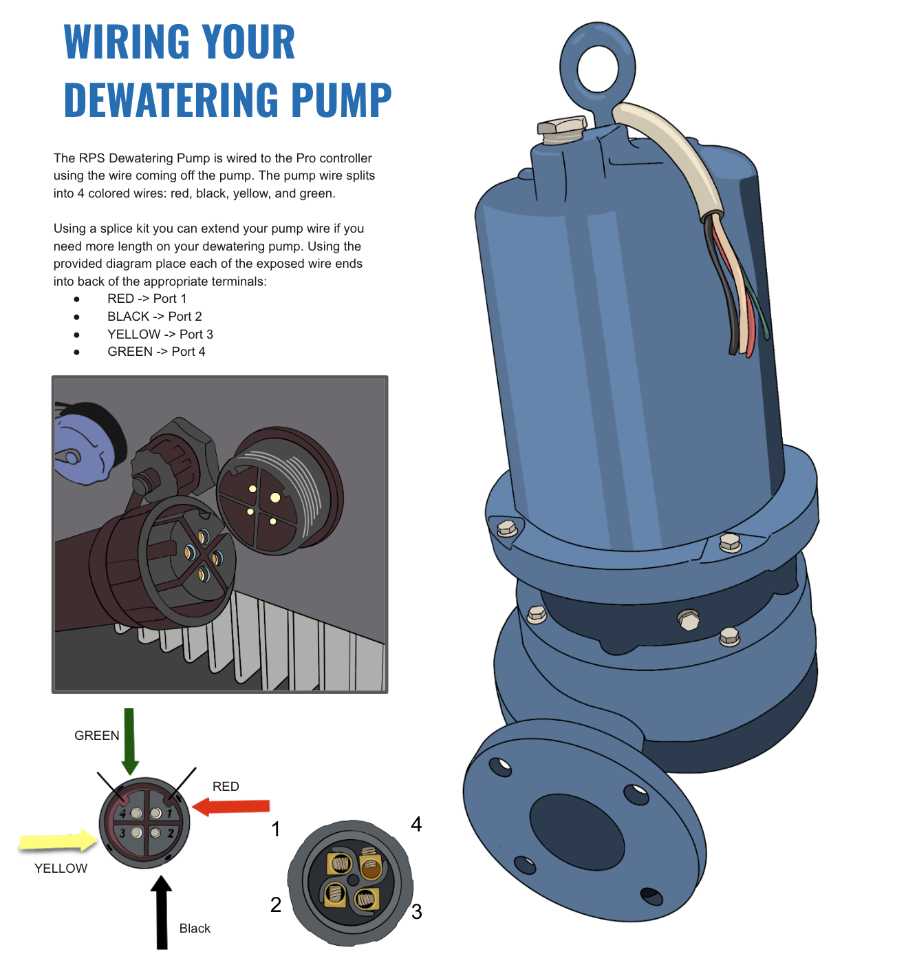
For most of the Pro Dewatering pump systems you will use 10 gauge / three conductor + ground (four wires).
Pro Irrigation XL 5 HP: Check with an RPS Engineer on the gauge of wire, 10 gauge is standard but a larger gauge may be needed depending on the HP and distance from pump to controller. We will perform a voltage loss calculation to finalize wire gauge.
Purchasing Wire
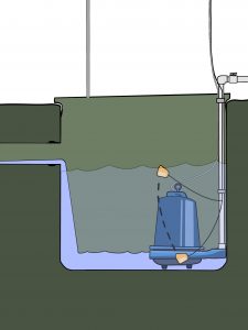
Dewatering pluming example
The type of pipe used for dropping a pump into a well depends on the drop depth, a deeper drop depth requires stronger, thicker walled pipe. Flow rate produced by the pump also influences the pipe diameter, ask our engineers if you are unsure what type and diameter pipe to use.


Your Pro Controller will monitor pump operation and shut the pump off before it can run dry. The controller is constantly monitoring the mix of amperage and voltage sent to the pump, and a sharp increase in amperage will alert the controller to a possible run-dry scenario, leading to pump shut-off.
Why A Reverse Action Pressure Switch Instead of a Regular Pressure Switch?
Our controller logic for tank full relies on a reverse action pressure switch.
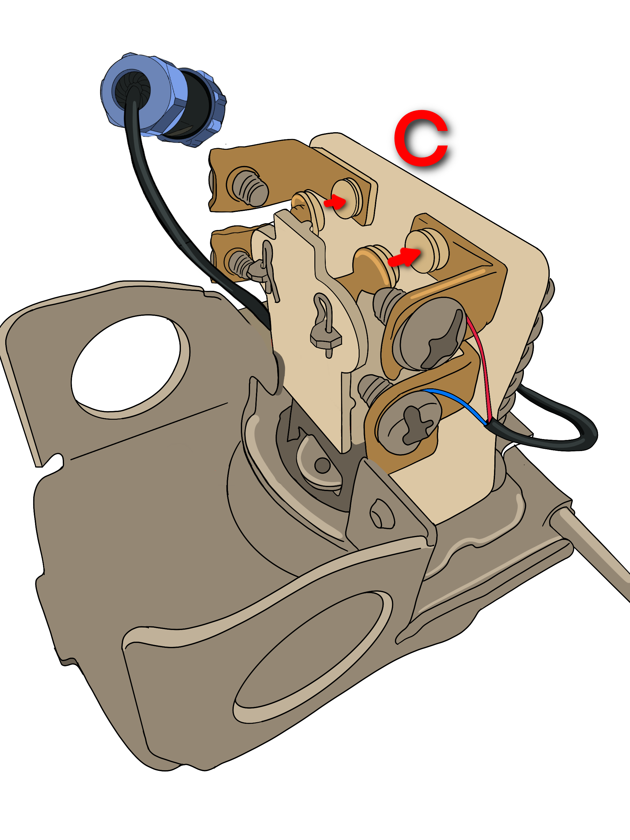
With a normal action pressure switch, when pressure is low a normal action pressure switches the contacts closed. When pressure is reached the contacts close.
Reverse action are reverse, when pressure is low the contacts are open. When pressure is reached the contacts close. When the contacts close the pump turns off.
Upon activation, your controller allows you to switch between solar power and 220v AC (Generator or Grid) automatically. You’ll be plugging into the AC Input Port on the bottom of your controller. You are going to wire out the Neutral and connect two hots (L1 and L2) to the L and N terminals in the 3 prong plug supplied in your kit.

Pro 500, 750, 1000, 1500, 2000, 3000
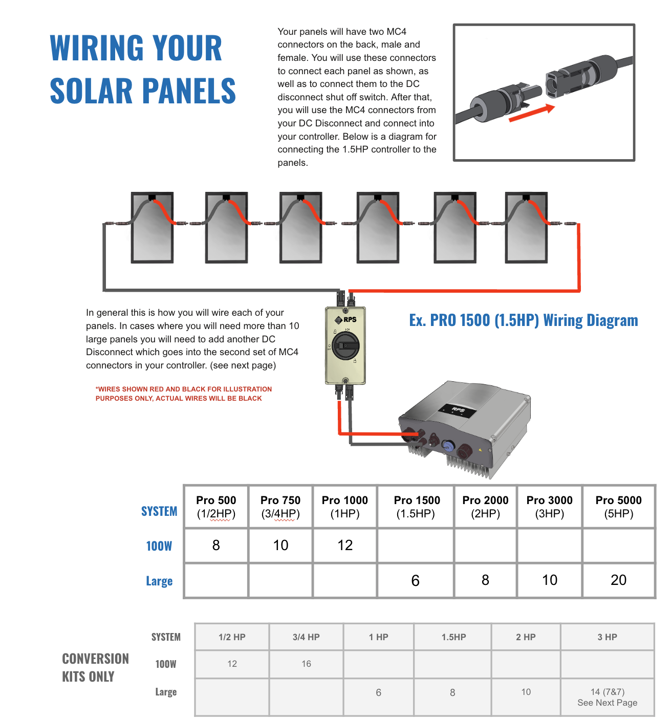
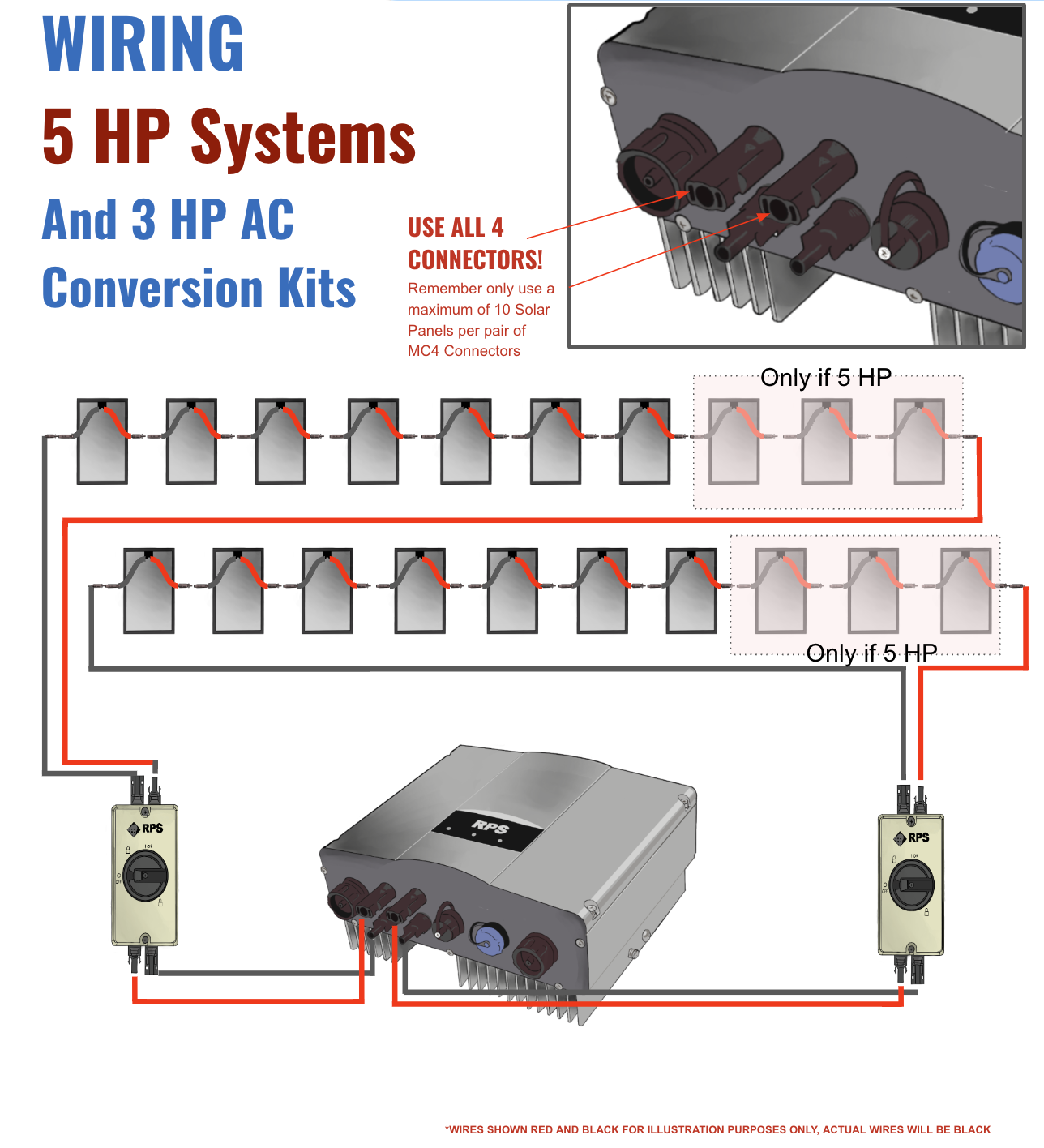
You’ll be connecting + wires to – wires in ‘series’ (panels can be oriented in different patterns for mounting purposes though).The positive (+) and negative (-) wires from your solar array will come into the DC Cut-off switch from the top. The short MC4 jumper wires included in your kit will connect at the bottom of the DC cut-off switch. All connections will be prepared before making the final connection to the DC inputs on the bottom of the solar pump controller. Mount your solar panels away from all possible shade, facing south at the proper tilt angle for your latitude.
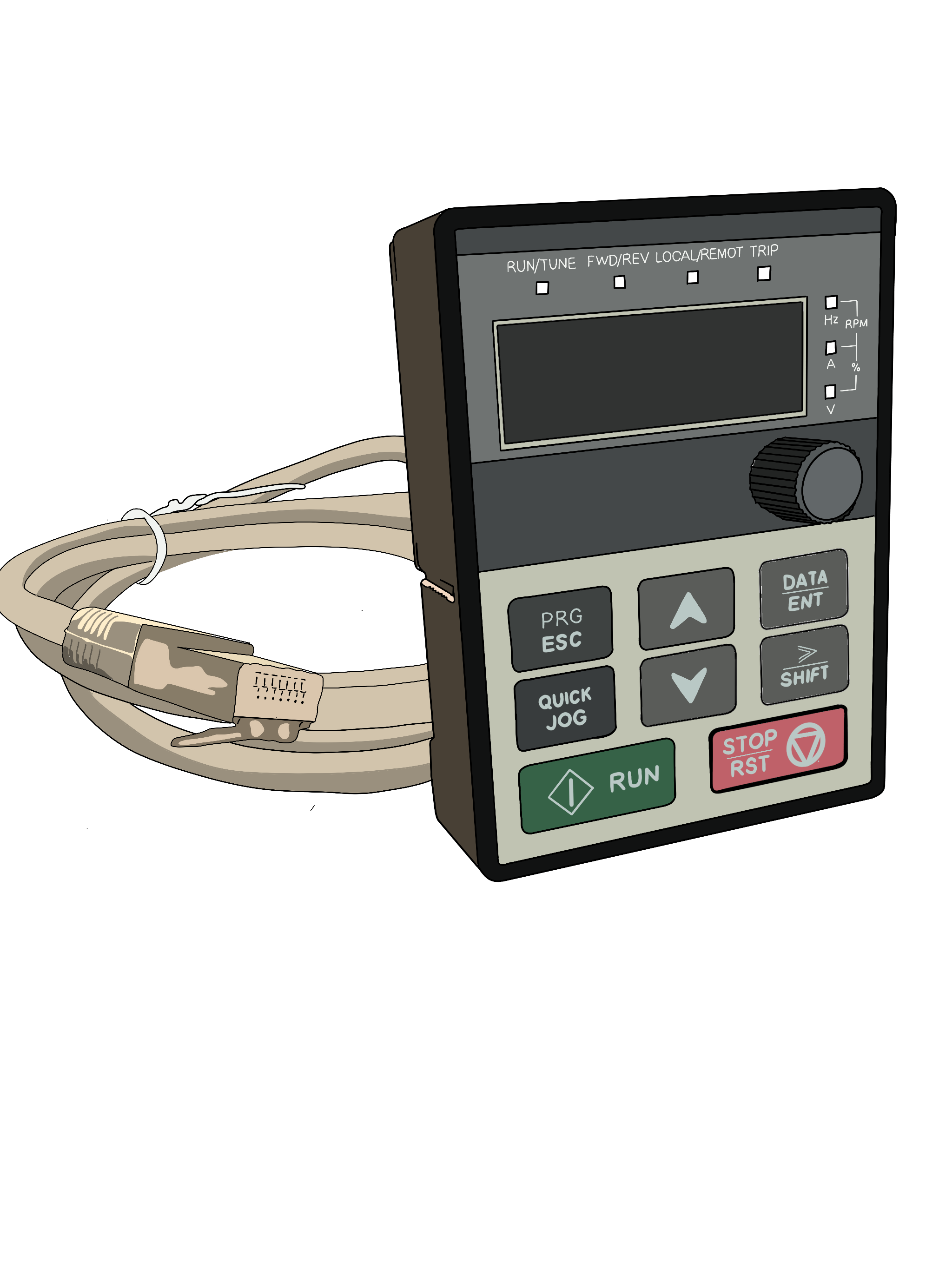
The Keypad included with your Pro System is used to check system runtime parameters, read fault status or stop condition details, or to reprogram the controller if system components change. Use the included connector cable and plug it into the back of the keypad. Unscrew the cover from the keyboard port and plug it in with the controller in the ON state.
If you are identifying a fault condition, connect the Keyboard and read the fault before performing a hard reset on the controller which will clear the fault. In most cases the system can run without ever having to connect the keypad. Most support calls are from customers who accidentally change settings when jogging through the various menus which can result in degraded performance or damage to the pump.
Operational State Parameters
The Keypad displays state parameters which assists in troubleshooting and system performance. To view these values connect the keypad to the controller while the system is running and press the SHIFT button to advance through the values. The various indicator lights to the right will change to indicate which value is being displayed.
All values other than set frequency and bus voltage will change in real time depending on solar conditions, time of day, and panel angle. The Keypad will display the values, after connecting, in the following order:
Frequency Top LED illuminated
RPM Top two LEDs illuminated
Current Middle LED illuminated
Percent Lower two LEDs illuminated
Voltage bottom LED illuminated
If you plan pumping into a tank and want the pump to shut off once the tank has filled, you’ll need an external shut off like a float switch or a mechanical float valve connected to a reverse action pressure switch. These floats will send a signal to the controller telling the pump to shut off once the tank is full, and another signal telling the pump to turn on if the tank is emptying.
With that being said, you could potentially swap out the current pump with a higher powered pump and keep the same controller. A higher horsepower pump would require more panels as well.
The Dewatering Pump can safely run dry and will shut off after a pre-programmed period of time. If you would like the pump to shut off just before running dry, you have the option of using a sump pump style float switch. The float switch will easily plug into the Pro Controller. You can adjust the length of the float switch wire to customize when the Dewatering Pump shuts off.
Indicator Lights
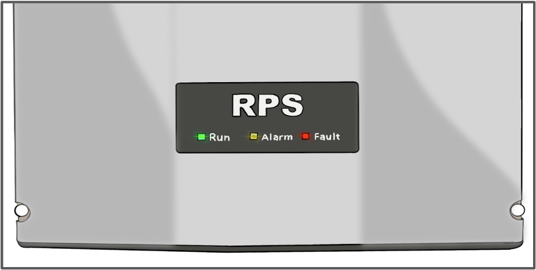
RUN – GREEN LED
- STEADY GREEN light means the pump motor is running normally between the minimum and maximum frequency.
BLINKING GREEN light means that your system is in startup mode.
ALARM – AMBER LED – This is a normal stop condition. When the ALARM light is illuminated an external condition is sending a signal to the controller to stop pumping water. Pumping will only resume when the external condition is resolved. The most common conditions causing a stop condition are:
- The tank is full.
- There is insufficient light to run your system.
- There is not enough water in the well (sucking air) and pump is waiting on a preprogrammed time delay before it can resume.
FAULT – RED LED
- If the FAULT light is illuminated it means a fault condition has occurred within the controller. Usually this indicates there is insufficient power to the controller to power up the pump (check that your solar panels are in full sun with zero shade. Even a small shadow can have significant impacts to water production).
- It can also indicate a system or programming fault that will place the controller in Standby to protect it. A fault condition can be temporary and may require resetting the controller by cutting system power with the DC disconnect, waiting 60 seconds (no lights on!) and then powering back on to resolve the fault.
- If the fault occurs repeatedly you will need to connect your Keypad to the controller to read out the fault condition displayed on the red seven segment LED on the keypad. RPS Support Engineers can help troubleshoot in cases of repeated faults.
